


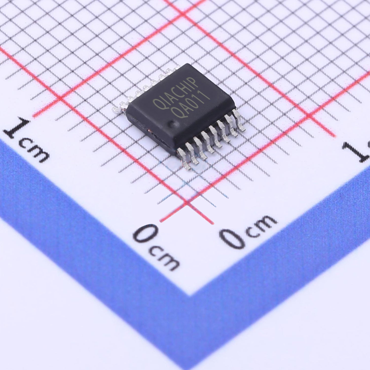
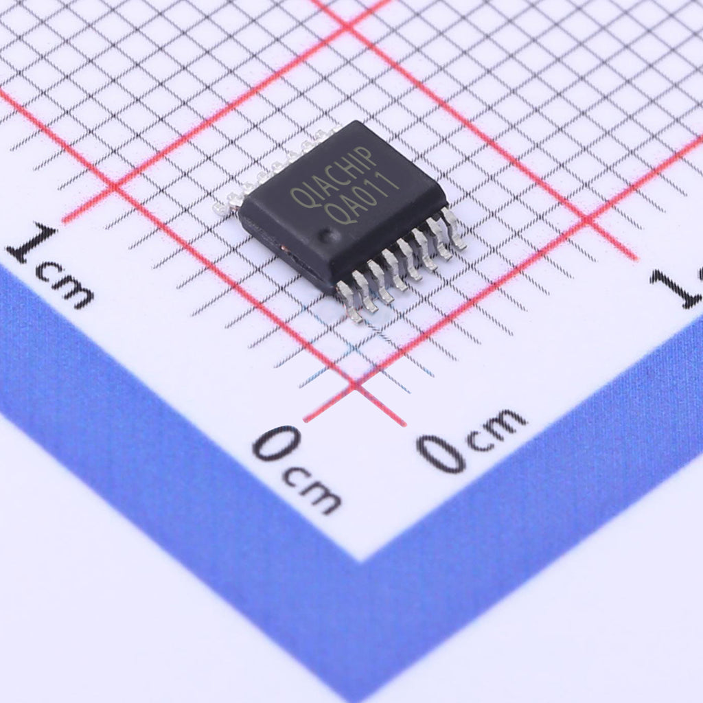
QA011 Receiver Module Decoding chip 433m 315m 1 channel Remote control switch EV1527 Decode IC QA-R-011 Datasheet Arduino DIY 2262 decoder
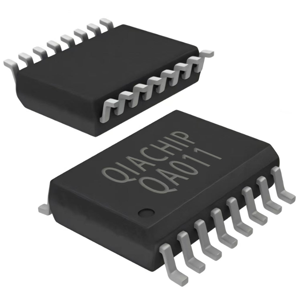
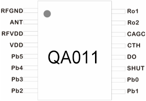
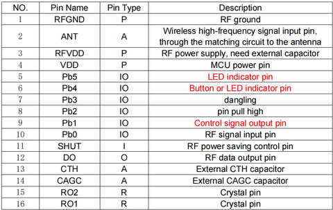
QA011
Single output with Decoding
Wireless Remote Control RF Receiver Chip
Features
1. Including RF receiver chip, commonly used in data transmission and control system
2. Can operate independently, without external MCU control
3. Compatible with fixed code coding chips: PT2262, EV1527,PT2264, SC1527, HS1527, RT1527, etc.
4. Automatic identification of coding chip type
5. Momentary, Toggle and Latched functions can be converted at will, without jumpers, long-term stability
6..Support PT2262 and EV1527 remote control mixed learning, no need to manually select
7. Code-to-code learning, no manual coding required
8. Built-in memory, safe and reliable
9. Ultra-wide working voltage
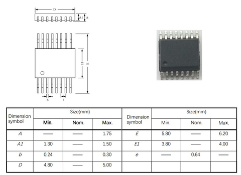
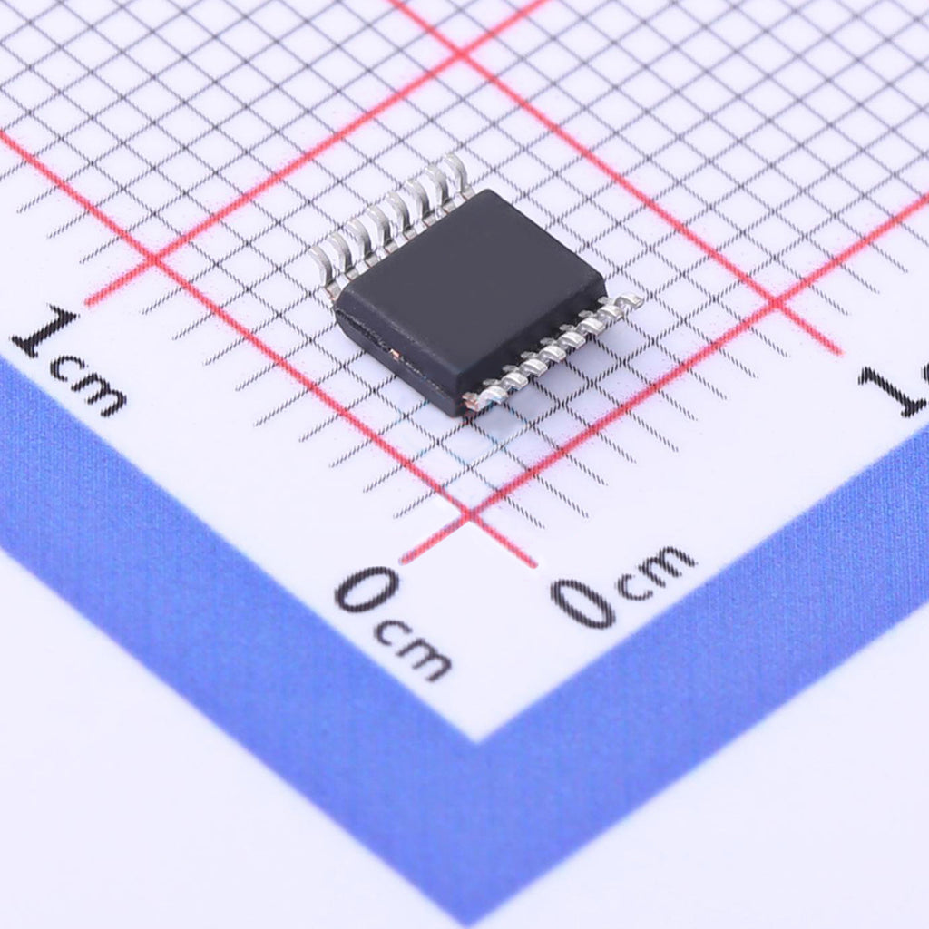
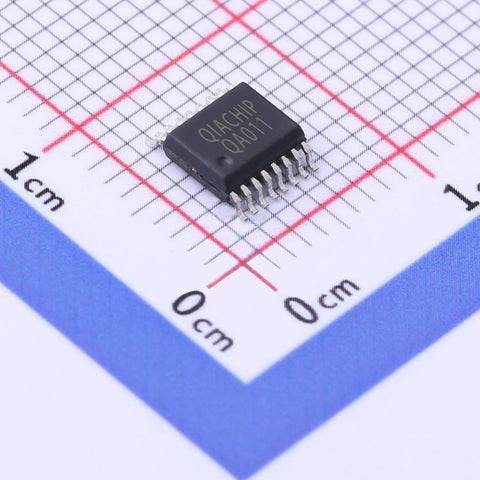
10. Adopt dense-pin SSOP16 package, small size, more suitable
for the application of small volume products
Application
- Wireless remote control switch
- Remote motor control
- security system
- Access control system
- Building community automation and fire protection
- Street light control system
- Smart Home Controller
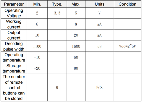
Performance parameters
ASK/OOK RF reception
Operating voltage: 2.0V - 5.0V
Frequency range: 300MHz - 450MHz
Receive sensitivity: -111dBm
Receive power consumption: 4.5-6.6mA
Standard CMOS interface control and decode data output
Description
Application circuit
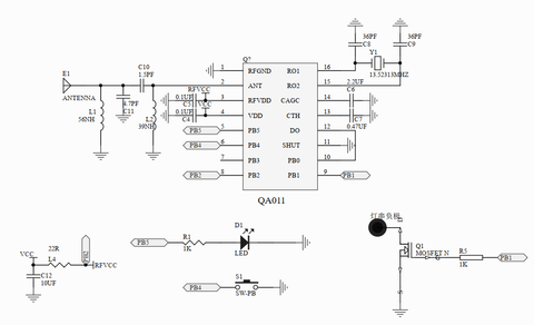
This application circuit uses the MOSFET as the control device, and uses the RF signal to control the on-off of the negative electrode of the circuit. The LED is the learning indicator of the RF remote control, clearing the data indicator of the RF remote control, the control mode setting indicator, and the decoding valid indicator of the receiving module; S1 is the button, as the control mode setting, the setting button of the RF remote control learning. Application example: When the QA011 chip receives the data of the remote control that has been learned, the LED light flashes, the PB1 pin will output a high level to control the conduction of the MOSFET.
Crystal oscillator can be provided by QIACHIP
Function description and mode setting
Clear code reset function: After pressing the learning button of the
module for 8 times, the MOSFET that controls the negative
electrode is turned off, and the indicator light flashes 6 times. After
clearing all stored RF remote control key values, the indicator light
of the module goes out.
Momentary mode: press the learning button of the module once,
and the LED indicator flashes once. When the LED indicator is on,
press the remote control button to be matched, and the LED
indicator of the module flashes continuously for 3 times, indicating
that the pairing is completed.
Then, press and hold the matched remote control button, the
MOSFET controlling the negative pole on the module will be turned
on, release the remote control button, and the MOSFET controlling
the negative pole on the module will be turned off.
Toggle mode: press the learning button of the module twice, and
the LED indicator flashes twice. After the LED indicator is on, press
the remote control button to be matched, and the LED indicator of
the module flashes continuously for 3 times, indicating that the
matching is successful.
Then, press the matched remote control button to turn on the MOSFET controlling the negative pole on the module. Press the same matched remote control button again to turn off the MOSFET controlling the negative pole on the module.
Latching mode: long press the module learning button for 3 times,
and the LED indicator flashes for 3 times. When the LED indicator
light is on, press the key (A) of the remote control to match. After the
LED indicator light flashes for 3 times, it will continue to be on, and
then press the key (B) of the remote control to match. The LED
indicator flashes for 3 times and then goes out, indicating that the
matching is successful.
Then, press the remote control button (A), the MOSFET controlling
the negative pole on the module will be turned on, and then press
the remote control button (A), the MOSFET state will not change.
Press the remote control button (B), the MOSFET controlling the
negative pole on the module will be turned off, and then press the
remote control button (B), the MOSFET state will not change.
Closing function with 5S delay: press the module learning button
4 times, and the LED indicator flashes 4 times. After the LED
indicator is on, press the remote control button for matching, and the
module LED indicator flashes continuously for 3 times, indicating
that the matching is successful.
Then, press the matched remote control button, and the MOSFET
controlling the negative pole on the module will be turned on. After
a delay of 5 seconds, the MOSFET controlling the negative pole on
the module will be turned off.
Closing function with 10S delay: press the module learning button
5 times, and the LED indicator flashes 5 times. After the LED
indicator is on, press the remote control button for matching, and the
module LED indicator flashes continuously for 3 times, indicating
that the matching is successful.
Then, press the matched remote control button, and the MOSFET
controlling the negative pole on the module will be turned on. After
a delay of 10 seconds, the MOSFET controlling the negative pole
on the module will be turned off.
Closing function with 15S delay: press the module learning button
6 times, and the LED indicator flashes 6 times. After the LED
indicator is on, press the remote control button for matching, and the
module LED indicator flashes continuously for 3 times, indicating
that the matching is successful.
Then, press the matched remote control button, and the MOSFET
controlling the negative pole on the module will be turned on. After
a delay of 15 seconds, the MOSFET controlling the negative pole
on the module will be turned off.
Closing function with 20S delay: press the module learning button
7 times, and the LED indicator flashes 7 times. After the LED
indicator is on, press the remote control button for matching, and the
module LED indicator flashes continuously for 3 times, indicating
that the matching is successful.
Then, press the matched remote control button, and the MOSFET
controlling the negative pole on the module will be turned on. After
a delay of 20 seconds, the MOSFET controlling the negative pole
on the module will be turned off.
Package
Precautions:
RF devices are voltage sensitive devices. If the power supply is unstable
or the ripple is large, add a filter to the power input to ensure that the power supply voltage does not exceed the maximum operating voltage of the product.
This device is an electrostatic sensitive device, anti-static measures must be used in transportation and use. When patching, make sure that the temperature does not exceed 245 degrees
It is recommended not to use a rubber-covered spring antenna in
application to ensure a better product yield. The product description is subject to change without notice.
Antenna
General application
For general applications, antennas can be directly adapted to
market specifications as follows:
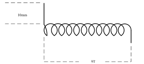
433M antenna
Wire length at welded end is 10mm; The total length of antenna
wire straightening is 170mm; Winding turns are 9 turns.
Click to buy antenna