User Manual
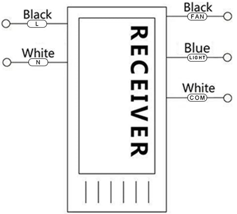
- Receiver Functions(Right Diagram)
|
AC IN L (Left Black) |
Input Live wire |
|
AC IN N (Left White) |
Input Neutral wire |
|
FAN (Right Black) |
Output Fan Live wire (Fan) |
|
LIGHT (Right Blue) |
Output Light Live wire (Light) |
|
COM (Right White) |
Output Neutral wire (Light & Fan Common connection) |
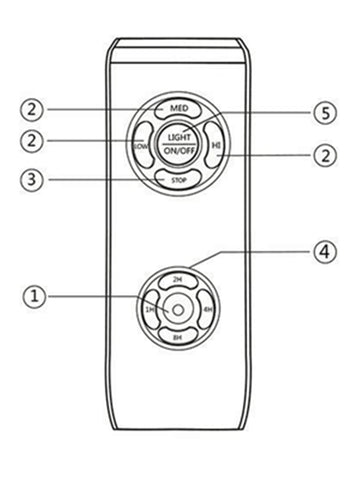
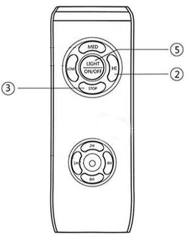
- Remote Control Functions (Right Diagram)
|
① LED Light |
Indicator LED Light |
|
② LOW/MED/HI |
Minimum, Medium, Maximum Fan speed |
|
③ STOP |
Stops Fan |
|
④ 2H/4H/8H/1H |
Fan & Light Timer |
|
⑤ Light ON/OFF |
Switch Light from on & off |
- Installation
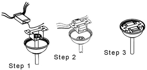
- Wiring diagram
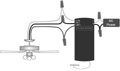
Specifications
|
Applications |
Light/Fan |
|
Operating Voltage |
110V/220V Depending on model |
|
Max Load Power |
<300W Ceiling Fan / <200W LED Light |
|
Standby Power consumption |
<0.5 W |
|
Working temperature |
-20℃~80℃ |
|
Control Method |
Remote control |
|
Wiring Method |
Live Wire & Neutral Wire |
- F&Q
Q: If you remote cannot control the receiver.
A: 1.Please turn off the power.
- Turn on the power again.
- Press and hold “LIGHT” (⑤)and “HI”(②) at the same
time within 5 seconds until the receiver beeps 3 times.
Q: Turn off the beep of the controller.
A: 1. Turn off the power. Then Turn on the power.
- Press and hold “STOP”(③) at the same time within 5 seconds until the receiver beeps 3 times.


Good Day,
how to address remote control unit and receiver when tow systems are installed close together, e.g. like in lage room?
How do the system determinate the correct receiver and sender?
BR
Achim